
Why Is My Solar System Underperforming? Causes and How to Fix It
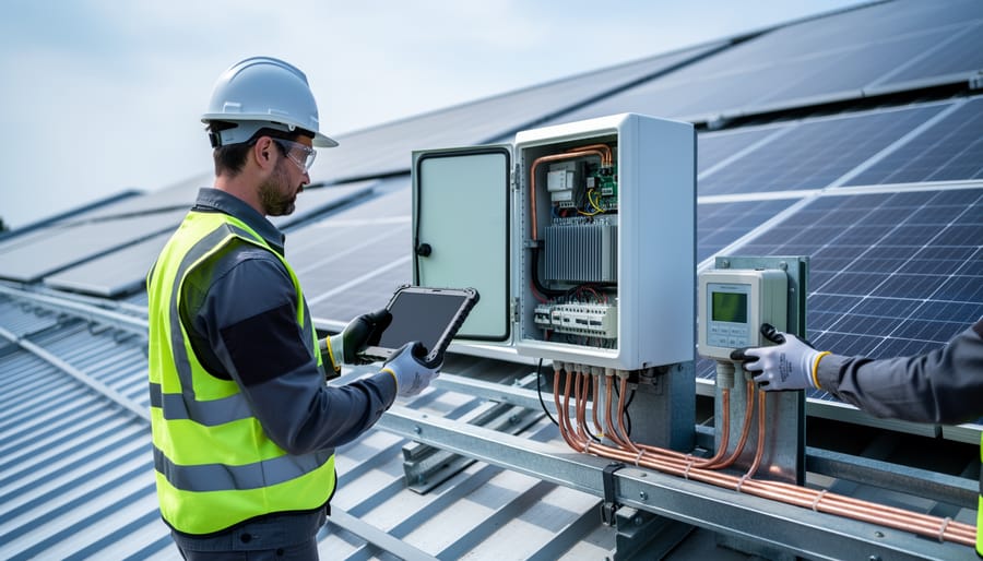
In most underperforming solar installations, the culprit is a single failed component: a malfunctioning inverter, shading that wasn’t accounted for during initial site assessment, or degraded electrical connections. Start your diagnostic by checking the inverter display or monitoring app for error codes. A blank screen or fault message immediately narrows the problem. If the inverter shows normal operation but power output remains low, measure string voltage at the combiner box to isolate whether the issue originates upstream at the array or downstream in the balance of system components.
Key Takeaway: Solar system repairs follow a structured triage: inverter diagnostics first, then array-level voltage checks, followed by connection integrity testing. Most failures cluster around inverters, soiling, and loose terminations, all of which contractors can address with standard tools and safety protocols.
The troubleshooting framework that follows walks through systematic root cause analysis, from the most common failures to rare edge cases. This structure reduces truck rolls, minimizes downtime for clients, and ensures repairs meet NEC 2023 standards and manufacturer warranty requirements. Critical safety note: always de-energize circuits before opening junction boxes or accessing DC-side components. High-voltage DC presents arc flash and shock hazards that require appropriate PPE and lockout procedures. If you encounter module-level damage, physical defects in racking that compromise structural integrity, or repeated inverter failures pointing to grid interaction issues, escalate to a licensed electrician or the original equipment manufacturer before proceeding.
Diagnosing Your Solar System Problems
The first step in effective solar system repair is distinguishing normal seasonal variation from genuine performance problems. Your monitoring system provides the clearest initial signal: production dropping more than 10% below historical averages for the same period typically indicates an issue requiring investigation. Most modern inverters and monitoring platforms display daily, monthly, and annual production data, compare current output against previous years adjusted for weather patterns.
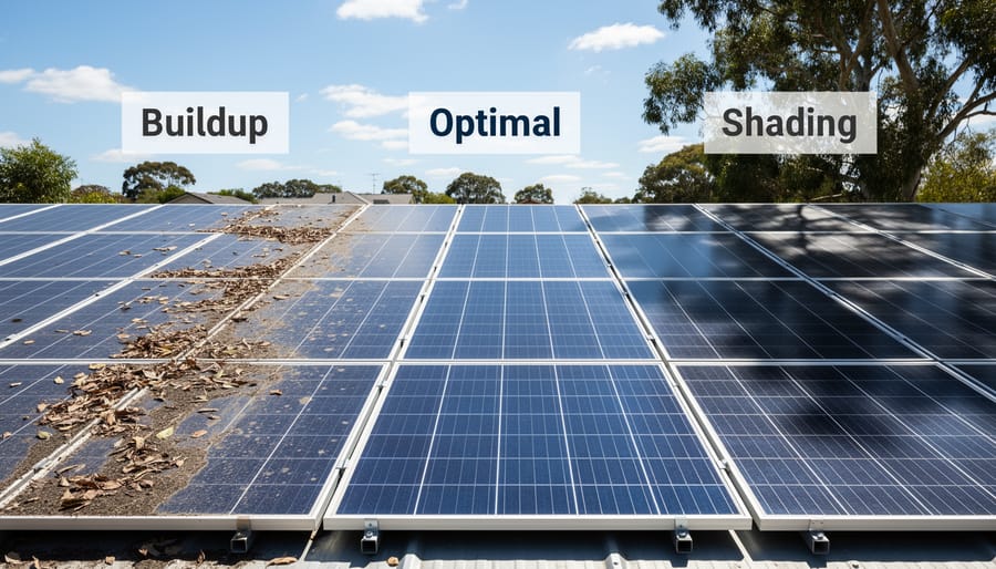
Physical inspection reveals problems monitoring data cannot detect. Walk your array looking for obvious damage: cracked glass, discolored cells forming brown spots or snail trails, burn marks around junction boxes, and loose or corroded wiring connections. Check mounting hardware for rust, loose bolts, or structural shifts. Note any new shading from tree growth, building additions, or debris accumulation. Panel soiling appears uniform across the array, whereas localized dirt buildup on specific panels suggests drainage or mounting angle issues.
Three key performance indicators signal repair needs. System efficiency, actual production compared to rated capacity under current irradiance conditions, should stay within manufacturer specifications (typically 80-85% of nameplate rating for systems over five years old). String voltage and current readings from the inverter interface reveal individual circuit problems: one underperforming string among several indicates localized damage rather than system-wide issues. Inverter error codes provide specific diagnostic information, consult your model’s manual to interpret fault messages correctly.
| Symptom Observed | Severity Level | Immediate Action |
|---|---|---|
| Production drop 10-25% below historical baseline | Moderate | Inspect panels for soiling; review monitoring data for string-level issues |
| Production drop exceeding 25% | High | Check inverter for error codes; examine all electrical connections |
| Visible panel damage or discoloration | High | Isolate affected panel; schedule professional inspection |
| Inverter offline or displaying fault codes | Critical | Document error codes; shut down system if safety risk indicated |
| Gradual decline of 1-2% annually | Normal | Continue regular monitoring; typical degradation rate |
Temperature anomalies detected through thermal imaging cameras identify hidden defects invisible to standard inspection. Hot spots exceeding 10°C above adjacent cells indicate failing bypass diodes, internal cell cracks, or connection resistance. This diagnostic tool proves particularly valuable for large commercial arrays where visual inspection alone misses subtle performance degradation across hundreds of panels.
Common Causes of Solar System Failure
Panel-Level Issues
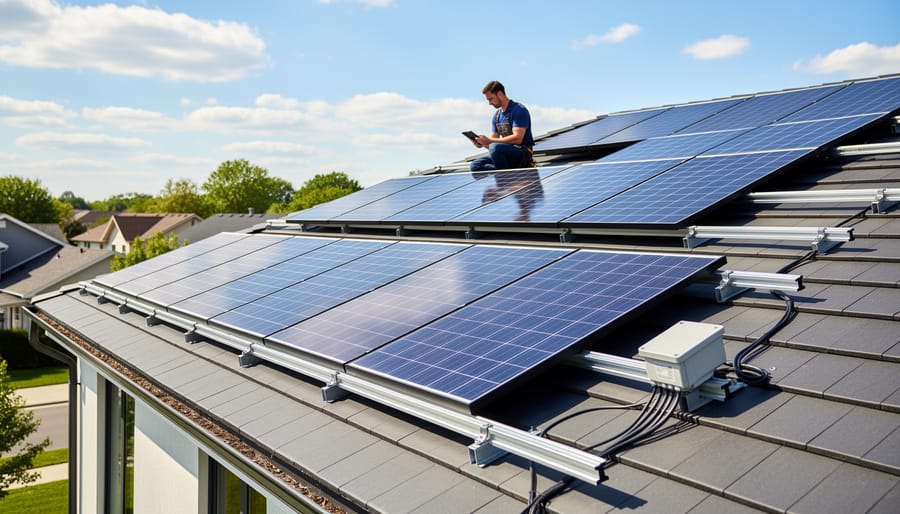
Photovoltaic panels develop several distinct failure modes that directly impact energy production. Microcracks in silicon cells, often invisible to the naked eye, create resistance pathways that reduce output by 2-10% per affected panel. These fractures typically stem from thermal cycling, installation stress, or hail impact. Hot spots emerge when individual cells generate excessive heat due to partial shading, manufacturing defects, or internal short circuits, temperatures can exceed 85°C, accelerating degradation and creating fire hazards.
Delamination occurs when the encapsulant separates from the glass or backsheet, allowing moisture infiltration that corrodes electrical connections and creates arc faults. You’ll notice yellowing or bubbling between layers. While the latest solar panel tech incorporates improved encapsulants and cell designs to resist these issues, older installations remain vulnerable.
Cell degradation manifests as gradual power loss beyond normal 0.5% annual decline rates. Potential-induced degradation (PID) causes voltage leakage to the frame in high-voltage systems, while light-induced degradation (LID) affects some cell types during initial exposure. Thermal imaging reveals these defects through temperature differentials, making infrared inspection essential for accurate diagnosis.
System Component Failures
Inverter failures represent the single most common system-level breakdown in solar installations. String inverters typically display error codes indicating DC overvoltage, ground faults, or arc detection events. Check for loose AC connections at the inverter output terminals, which cause intermittent shutdowns and thermal stress on internal components. Microinverters fail gradually, with individual units dropping offline rather than shutting down the entire array.
Power optimizers experience firmware corruption, communication failures, and rapid shutdown circuit malfunctions. Monitoring platforms show optimizer dropouts as data gaps for specific panels, while the string continues operating at reduced capacity. Failed optimizers require replacement rather than repair.
Combiner boxes develop corrosion at terminal blocks, particularly in coastal or high-humidity environments. Inspect for discolored connections, melted insulation, or visible arcing damage. Loose fuse holders create high-resistance contact points that generate heat without triggering overcurrent protection.
DC disconnect switches fail mechanically from repeated cycling or develop contact resistance from oxidation. Test voltage drop across closed contacts, readings above 0.5V indicate replacement needed. String-to-string voltage imbalances exceeding 5% typically signal connection degradation between panels or at junction boxes.
Environmental and External Factors
Soiling accumulation reduces panel efficiency by blocking sunlight from reaching photovoltaic cells. Dust, pollen, bird droppings, and industrial pollutants create a film that can decrease output by 5-25% depending on location and rainfall frequency. Desert and agricultural areas experience the most severe soiling, requiring more frequent cleaning intervals.
Shading from new vegetation growth or adjacent construction eliminates production from affected cells. Even partial shading on a single panel can reduce entire string output due to series wiring configurations. Trees that were small at installation often grow to cast problematic shadows within 5-7 years.
Weather damage from hail, high winds, or flying debris causes cracks and delamination. Hurricane-force winds can lift panels or compromise mounting hardware. Wildlife interference includes nesting birds beneath arrays, squirrels chewing wiring insulation, and rodents creating fire hazards through exposed conductors.
Step-by-Step Solar System Repair Process
Safety Preparation and System Shutdown
Before beginning any solar system repair work, power down the entire array using the emergency shutdown switch located near the inverter or main service panel. Wait a minimum of five minutes after shutdown to allow capacitors to fully discharge, as residual voltage can persist even when the system appears off. Once the system is de-energized, apply proper lockout/tagout and PPE protocols by placing a lock on the disconnect switch and posting warning tags to prevent accidental re-energization while you work.
Warning: Work on solar systems must comply with OSHA electrical safety standards and NEC Article 690 requirements, violations can result in serious injury or void system warranties.
Required personal protective equipment includes voltage-rated insulated gloves (minimum 1000V rating), safety glasses with side shields, arc-rated clothing, and non-conductive footwear. Use a non-contact voltage tester to verify the system is truly de-energized before touching any wiring, testing both DC and AC sides of the inverter. For roof-mounted systems, also implement fall protection measures including a properly anchored harness and appropriate ladder safety protocols.
Panel Cleaning and Inspection
Effective panel cleaning requires the right approach to avoid damage while maximizing light transmission. Begin cleaning early morning or late evening when panels are cool, thermal shock from cold water on hot panels can cause microcracks. Use deionized or distilled water with a soft-bristle brush or squeegee; avoid abrasive materials that scratch anti-reflective coatings. For stubborn soiling, add a pH-neutral cleaning solution specifically formulated for solar panels. Never use high-pressure washers exceeding 40 psi, as excessive force can compromise junction boxes and frame seals.
During cleaning, conduct systematic visual inspection of each panel. Check for visible cracks, discoloration, or “snail trails”, brown streaks indicating cell degradation. Examine frame integrity, looking for corrosion or separation from the glass. Inspect all electrical connections for signs of arcing, melting, or water intrusion in junction boxes. Use thermal imaging if available to identify hot spots indicating failing cells or bypass diodes. Document any anomalies with photographs and exact panel locations for tracking degradation patterns over time.
Electrical Component Testing
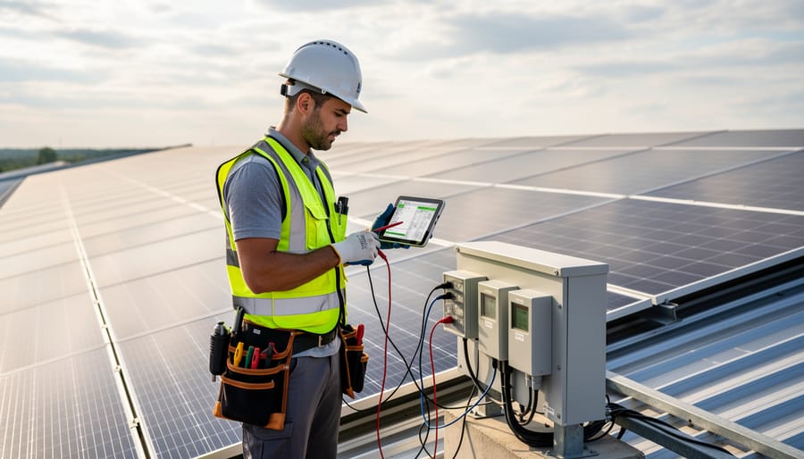
Testing electrical components requires methodical voltage, current, and resistance measurements to isolate faults. Start with your digital multimeter set to DC voltage mode. At the inverter input terminals, measure the string voltage with the system energized, compare readings against the panel specifications multiplied by the number of panels in series. Voltage significantly below expected values indicates open circuits, broken connections, or failed panels within that string.
Check individual panel output at the junction box using voltage and current measurements. Under full sun conditions, open-circuit voltage should match manufacturer specs (typically 30-50V per panel). Short-circuit current testing requires specialized equipment and training, never attempt this without proper safety protocols. Instead, measure operating current at the combiner box to verify each string contributes expected amperage.
Test inverter functionality using built-in diagnostic modes if available. Most modern inverters display error codes indicating specific faults, consult the technical manual for interpretation. Measure AC output voltage and frequency at inverter terminals to confirm proper grid synchronization. Use a clamp meter on AC output wiring to verify actual power delivery matches inverter display readings, revealing potential metering inaccuracies or conversion losses.
Inspect all connection points for continuity and resistance. Corroded MC4 connectors or loose terminal blocks create high-resistance points that generate heat and reduce efficiency. Thermal imaging cameras identify these problem areas quickly, showing hot spots invisible to standard testing.
Component Replacement Procedures
Component replacements must follow manufacturer specifications and local electrical codes. Before installing any replacement component, verify compatibility with existing system voltage, power ratings, and communication protocols, mismatched equipment can damage interconnected devices or create safety hazards.
For inverter replacement, document all wiring configurations before disconnecting. Match wire gauge and torque specifications during reinstallation, and confirm proper grounding connections. String inverters typically require two technicians due to weight and complexity; microinverters allow individual replacement without full system shutdown. After installation, verify AC and DC connections meet code requirements and test ground fault protection systems.
Optimizer replacements follow similar protocols, photograph original wiring, match polarity carefully, and apply dielectric grease to outdoor connectors. Most optimizers mount directly to racking, requiring panel removal for access. Test communication with the monitoring platform before completing reassembly.
Connector replacements address common failure points in system setup. Use quality MC4 connectors rated for outdoor exposure, crimped according to manufacturer specifications. Avoid cheap connectors that corrode rapidly. Splice repairs violate most electrical codes; replace the entire cable section instead.
Panel replacement becomes necessary when efficiency drops exceed 20% from degradation or physical damage creates safety risks. Matching replacement panels to original specifications prevents voltage mismatches that reduce string performance.
System Restart and Performance Verification
After completing repairs, never simply flip the main disconnect back on. Start with a methodical restart sequence to protect equipment and personnel. First, verify all panel connections are secure and junction boxes are properly sealed. Check that any replaced components are firmly mounted and all wire terminals are tight. Confirm your multimeter readings show expected voltage levels before energizing the system.
Bring the system online in stages: close the DC disconnect first, then monitor the inverter display as it initializes. Watch for error codes during the startup cycle, most inverters run self-diagnostics that will flag lingering issues. Once the inverter shows normal operation, close the AC disconnect and verify grid connection.
Monitor production data continuously for the first 48 hours. Compare real-time output against your baseline measurements from before the problem occurred. Production should match expected values for current irradiance conditions, if you’re still seeing 15-20% below normal on a clear day, you haven’t isolated the root cause. Review inverter logs for intermittent faults that might indicate partial fixes or secondary issues requiring attention.
Preventive Maintenance Best Practices
Regular Monitoring and Data Analysis
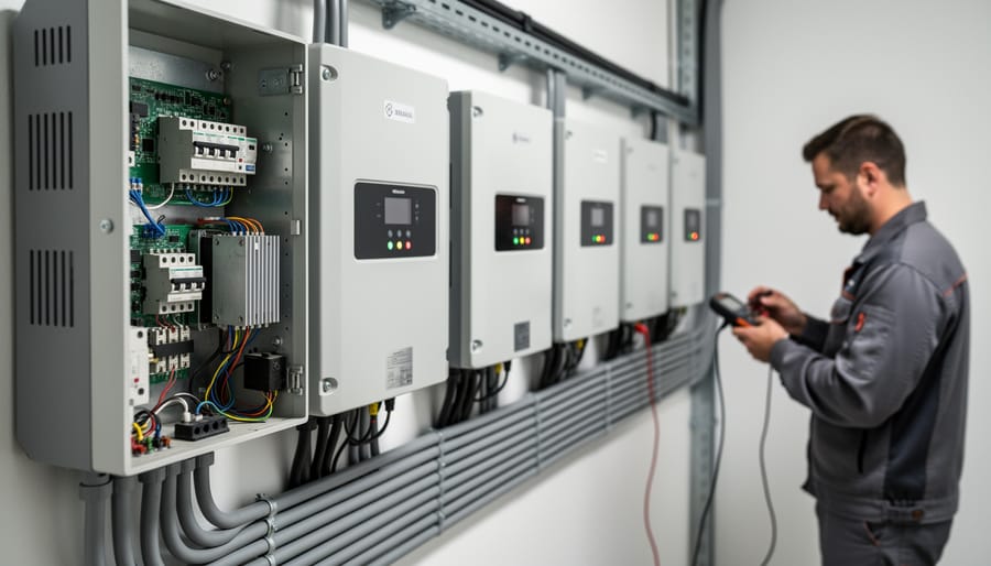
Modern monitoring platforms are your front-line defense against costly system failures. Set up real-time tracking through your inverter’s monitoring portal or dedicated asset management software that aggregates production data across all strings. Configure alerts for production drops exceeding 10%, inverter faults, and grid disconnections, these catch problems within hours, not months.
Establish your baseline during the first 60 days of operation when weather patterns are stable. Record average daily production per kilowatt installed, typical peak output times, and string-level performance ratios. Compare actual production against predicted yield from your design software monthly. A sustained deviation of 15% or more signals deterioration requiring investigation.
For commercial installations, integrate monitoring into broader solar asset management workflows. Track performance metrics alongside maintenance logs, warranty data, and component histories. This consolidated approach reveals patterns linking specific hardware to recurring issues, helping you prioritize repairs by financial impact rather than simply responding to alerts as they arrive.
Scheduled Inspection and Cleaning Programs
Establishing a routine inspection and cleaning schedule prevents most repair issues before they escalate. The frequency depends on your environment, not arbitrary calendar dates.
Climate-Based Inspection Intervals
Desert and arid regions require monthly visual inspections and quarterly cleaning due to rapid dust accumulation that can reduce output by 15-25% between cleanings. Systems in these environments also experience accelerated thermal cycling that stresses electrical connections.
Humid coastal areas need quarterly inspections focusing on corrosion points, with semi-annual cleaning unless heavy pollen seasons dictate more frequent attention. Salt spray accelerates degradation of mounting hardware and junction boxes.
Moderate climates with seasonal precipitation typically perform well with semi-annual inspections and annual cleaning, though autumn leaf fall or spring pollen may require additional maintenance windows.
System-Specific Considerations
Commercial flat-roof installations collect debris in valleys and edges, requiring quarterly perimeter clearing and semi-annual full cleaning. Ground-mounted arrays in agricultural areas need monthly fence-line vegetation management and quarterly inspections for pest damage to wiring conduits.
Residential roof systems with steeper tilts benefit from rain self-cleaning but still require annual professional inspections to identify mounting point degradation, flashing failures, and electrical connection integrity that homeowners cannot safely assess.
Document every inspection with dated photos of panel conditions, inverter readings, and any observed changes. This maintenance record proves invaluable for warranty claims and tracking degradation patterns that predict future component failures.
When to Call a Professional
Certain repairs demand professional expertise regardless of your technical skills. High-voltage electrical work, including inverter replacement or combiner box servicing, carries serious shock and arc-flash risks that require specialized safety training and equipment. Roof-mounted system repairs involve fall hazards that certified technicians are equipped to handle through proper anchoring systems and safety protocols. Any work on systems still under warranty should be performed by authorized service providers, as DIY repairs typically void manufacturer coverage and may create liability issues.
Note: If your system is producing less than 70% of expected output or if you detect burning odors, arcing sounds, or visible component damage, immediately shut down the system and contact a certified technician before attempting diagnosis.
Professional intervention becomes essential when diagnostic tools indicate problems beyond basic troubleshooting. Thermal imaging revealing hot spots across multiple panels, ground fault indicators showing persistent errors, or inverter fault codes pointing to internal failures all require specialized diagnostic equipment and replacement procedures. Licensed electricians or certified solar technicians carry the proper testing instruments, replacement inventory, and technical documentation to efficiently resolve complex issues that would take homeowners days to troubleshoot.
Warranty considerations often make professional service the economically rational choice. Most inverter manufacturers require certified technician installation of replacement units to maintain coverage, and attempting self-repair forfeits that protection. For systems financed through property-assessed clean energy (PACE) programs or power purchase agreements, maintenance contracts often mandate professional service. When searching for qualified help, regional specialists such as solar installers in Maryland typically offer diagnostic services and can provide accurate repair estimates based on your system’s configuration.
The cost-benefit analysis favors professionals when repair complexity exceeds your available time and tools. A certified technician completes inverter replacement in two hours versus a full weekend of research and potential mistakes, and their work carries insurance protection against installation errors.
Frequently Asked Questions About Solar System Repair
How much does solar system repair typically cost?
Repair costs vary widely depending on the issue, ranging from $200-500 for basic electrical work to $2,000-5,000 for inverter replacement. Panel replacement costs depend on the number of affected modules and whether warranties cover the expense. Most diagnostic visits run $150-300.
Does my warranty cover solar system repairs?
Equipment warranties typically cover manufacturing defects for 10-25 years, while workmanship warranties from your installer usually last 1-10 years. Review your warranty documents to determine coverage, as self-inflicted damage, improper maintenance, or normal wear often fall outside warranty protection.
How long do solar system repairs take?
Simple repairs like cleaning or tightening connections can be completed in a few hours. Inverter replacements typically take one day, while panel replacements may require two to three days depending on system size and accessibility.
Will repairs restore my system to original performance?
If degradation hasn’t occurred, repairs can restore full performance. However, panels naturally lose 0.5-1% efficiency annually, so a five-year-old system operating at 95% of original output after repairs is performing as expected, not underperforming.
Beyond these common concerns, understanding that most solar systems require minimal intervention over their lifespan helps set realistic expectations. Professional repairs address acute failures, while preventive maintenance handles gradual performance drift. The key is catching issues early through consistent monitoring, which allows you to schedule repairs proactively rather than responding to system failures during peak production months.
Addressing solar system underperformance promptly protects both your investment and long-term energy production. The diagnostic framework and repair methodologies outlined here enable you to identify root causes systematically, implement appropriate fixes safely, and prevent recurring issues through structured maintenance protocols.
Most solar system failures result from identifiable, repairable causes rather than complete system obsolescence. Whether you’re managing a single residential installation or a portfolio of commercial systems, establishing regular monitoring routines and scheduled inspections catches problems before they compound into costly failures.
Document every repair, track performance metrics consistently, and maintain detailed service records. These practices not only optimize current system performance but also inform better decisions for future installations. Begin implementing a preventive maintenance schedule today, the reduction in emergency repairs and production losses will justify the effort within the first year.