
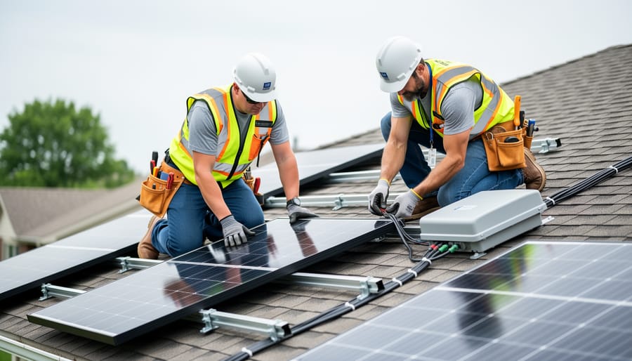
Solar Power Installation Step by Step: Professional Guide to System Setup
Solar power installation follows a structured five-phase process from site assessment through final commissioning, typically requiring two to four days for residential systems and one to three weeks for commercial arrays. Professional installers follow this procedural framework to ensure compliant, safe, and efficient grid-connected photovoltaic systems that meet electrical codes and utility interconnection standards.
The process demands technical precision at every stage. Successful installations hinge on accurate structural analysis, proper equipment selection aligned with 2026 solar panel tech specifications, meticulous electrical work, and rigorous testing protocols. Field conditions vary significantly across projects, but the core methodology remains consistent across residential, commercial, and utility-scale deployments.
This guide provides the complete step-by-step installation sequence used by top solar installers in 2026. Each phase addresses specific technical requirements, from mounting system integration through inverter commissioning and utility approval. The framework covers mandatory safety protocols, equipment staging procedures, module assembly techniques, DC and AC electrical connections, and final system verification steps that confirm optimal performance.
Whether you’re training new installation crews or refining field procedures, this reference breaks down the mechanical, electrical, and verification tasks into discrete, actionable steps. The goal is straightforward: deliver a fully operational solar array that meets all code requirements, performs to specification, and passes inspection on the first attempt.
Key Takeaway: Successful commissioning requires documented verification of insulation resistance (>1MΩ residential, >10MΩ commercial), open-circuit voltage within 5% of calculated values, and inverter functionality across all MPPT inputs. Any measurement outside these ranges indicates installation defects requiring immediate correction before system activation.
Pre-Installation Requirements and Site Assessment
Before any equipment reaches the roof, solar professionals must complete a comprehensive evaluation process that determines feasibility, defines system specifications, and secures regulatory approvals. Rushing this phase creates installation delays, safety hazards, and code violations that can stall projects for weeks.
Start with a thorough site evaluation that documents shading patterns throughout the day and across seasons using a solar pathfinder or digital shade analysis tool. Record roof orientation, pitch angle measured with an inclinometer, and available installation area. Photograph existing roof conditions, noting material type, age, and any visible damage that requires repair before installation. For ground-mount systems, assess soil conditions, drainage patterns, and setback requirements from property lines.
Structural engineering assessment is non-negotiable for roof-mounted arrays. Calculate dead load and live load capacity, factoring in the weight of panels, racking, snow accumulation, and wind uplift forces specific to your climate zone. Typical residential crystalline silicon panels with aluminum racking add 3 to 4 pounds per square foot. Most modern residential roofs handle this easily, but older structures, especially those with damaged trusses or undersized rafters, may require reinforcement. Commercial flat roofs often need ballasted systems or engineered attachments designed by a licensed structural engineer.
Electrical system capacity analysis determines whether the existing service panel can accommodate the solar interconnection. Measure the main breaker rating and bus bar rating, then apply the 120 percent rule: the sum of the main breaker plus the solar breaker cannot exceed 120 percent of the bus bar rating. A 200-amp panel with a 200-amp main breaker has a 240-amp limit (200 × 1.2), allowing a maximum 40-amp solar breaker. Systems exceeding this threshold require a service upgrade or alternative interconnection method such as a line-side tap.
Pre-installation documentation requirements include:
- Building permits from the authority having jurisdiction with stamped engineered drawings
- Electrical permits specifying inverter specifications and interconnection method
- Utility interconnection application with single-line diagram and site plan
- Homeowner association approval if applicable, with aesthetic compliance verification
- Structural engineering calculations and roof attachment load analysis
- Fire setback plan showing required access pathways per local fire code
Utility interconnection agreements define grid connection terms, net metering rates, and production metering requirements. Submit this application early, as utility review periods range from two weeks to three months depending on system size and local queue length. The agreement specifies whether you need a bidirectional meter upgrade and identifies any required utility-side equipment modifications.
Verify all permits are issued and posted on-site before scheduling the installation crew. Missing documentation halts work immediately during inspection and creates costly project delays that damage client relationships.
Essential Tools, Materials, and Equipment
Professional solar installations require a comprehensive toolkit spanning mechanical, electrical, and safety categories. Having the complete inventory on-site before starting prevents delays and ensures work quality.
Power tools form the mechanical backbone of installations. You’ll need a cordless impact driver (18V minimum) for lag bolts and mounting hardware, a circular saw with metal-cutting blade for conduit and rail cuts, and a hammer drill for concrete anchors on commercial flat roofs. A torque wrench calibrated to manufacturer specifications is mandatory for proper panel clamp installation, over-tightening damages frames while under-tightening creates hot spots.
Measuring and layout instruments ensure precision. A laser level establishes rail alignment across long roof runs. Digital multimeters capable of measuring up to 600VDC verify string voltages and detect polarity errors. Infrared thermometers identify loose connections during commissioning. A non-contact voltage tester confirms circuits are de-energized before work begins.
Mounting hardware varies by roof type but typically includes stainless steel lag bolts (5/16″ × 3″ for composition shingle roofs), flashing boots sized to your attachment method, L-feet or flush-mount brackets, aluminum rails cut to length, and stainless mid and end clamps. Commercial installations add ballasted racking systems or structural penetrations with appropriate waterproofing.
Electrical components comprise the system’s nervous system. Stock MC4 connectors, 10AWG and 8AWG USE-2 wire for string runs, appropriately rated combiner boxes, AC and DC disconnects meeting local code, grounding lugs and copper grounding wire, and conduit (typically 3/4″ EMT or Schedule 40 PVC depending on exposure). Keep wire strippers, crimpers, and heat-shrink tubing in your electrical kit.
Safety equipment is non-negotiable. OSHA-compliant fall protection harnesses, roof anchors rated for your weight plus tools, electrical PPE including insulated gloves rated for system voltage, safety glasses, and hard hats protect your crew. Commercial jobs require guardrail systems or warning lines on flat roofs.
Specialized equipment like cable pullers, conduit benders, and fish tape streamlines installations, while roof staging or scaffolding provides safe material staging on complex projects.
Critical Safety Protocols and Warnings
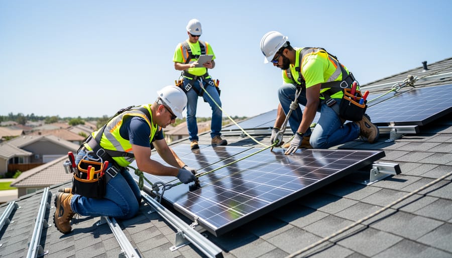
Solar installation work combines elevated work environments with high-voltage electrical systems, creating compounded hazards that demand strict adherence to safety protocols. Before any crew member ascends to a roof or handles electrical components, the site supervisor must verify that all required safety systems are in place and operational.
Warning: Solar installations involve lethal DC voltage levels exceeding 600V and fall hazards from heights, both can cause immediate fatalities without proper safety systems and training.
Fall protection is mandatory for any work performed above six feet per OSHA 1926.501 standards. Install perimeter guardrails, personal fall arrest systems with properly anchored lifelines, or safety net systems before workers access the roof. Each harness must be inspected daily for frayed webbing, bent D-rings, or damaged hardware. Verify roof load capacity through structural calculations before placing equipment, many residential roofs cannot support concentrated loads exceeding 20 pounds per square foot without reinforcement.
Electrical safety begins with lockout/tagout procedures. De-energize all AC circuits at the main service panel and verify zero voltage with a calibrated multimeter before making connections. Tag all disconnects with the installer’s name and date. Remember that solar arrays generate DC power whenever light strikes the modules, so string circuits remain energized even with inverters shut down. Workers must wear voltage-rated gloves when handling exposed conductors and use insulated tools rated for the system voltage.
Required personal protective equipment includes hard hats, safety glasses, electrical-rated gloves, non-slip footwear with ankle support, and fall protection harnesses. When working with new inverter features involving high-frequency switching, add hearing protection during commissioning tests.
Stop work immediately if weather conditions deteriorate, never install during rain, high winds exceeding 25 mph, lightning within ten miles, or when roof surfaces are wet or icy. These conditions compromise both fall protection and electrical safety, creating unacceptable risk levels that no schedule pressure justifies.
Step-by-Step Solar Installation Process
Step 1: Install Mounting Rails and Attachments
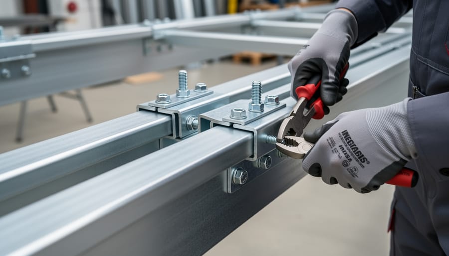
Begin mounting system installation by verifying the engineered rail layout matches the site conditions documented during your assessment. Use a stud finder or rafter probe to locate and mark rafter centers at each planned attachment point, confirming 16-inch or 24-inch spacing typical in residential construction. Mark locations 6 to 12 inches from the roof peak to avoid ridge board interference.
Install roof attachments using the flashing method specified for your roof type. For composition shingles, slide L-foot flashing under the shingle course above each attachment point, ensuring proper overlap with surrounding shingles. Position the lag bolt through the attachment bracket center, drill a pilot hole into the rafter center (typically 5/16-inch for 3/8-inch lag bolts), and drive the lag bolt to manufacturer torque specifications, usually 25 to 30 foot-pounds. Never rely on roof sheathing alone; every attachment must penetrate a structural rafter member at least 2.5 inches.
Apply polyurethane sealant around each flashing perimeter and beneath the shingle overlap to prevent water intrusion. Install attachments across the entire array footprint before mounting rails, working from bottom to top of the roof section.
Mount rails to the installed attachments using stainless steel hardware, maintaining proper rail spacing per module specifications. Use a laser level or string line to verify rails are parallel and coplanar within 1/4 inch across the array. Confirm rail ends have proper clearance from roof edges and penetrations, typically 6 inches minimum per building code requirements.
Step 2: Position and Secure Solar Panels
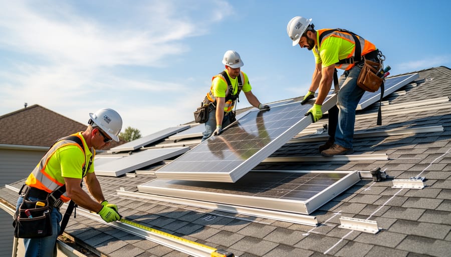
Begin panel placement once all mounting rails pass levelness and torque checks. Never attempt to lift modules in winds exceeding 20 mph or on wet surfaces. Use a properly rated roof hoist or manual lifting team of at least two installers per panel to prevent drops and worker injury.
Position the first panel at the starting corner established in your layout plan, typically the lower array corner farthest from roof access. Verify module orientation by checking the junction box location matches your electrical design, improper orientation creates wiring complications later. Maintain manufacturer-specified spacing between modules, typically 0.5 to 1 inch horizontally and vertically, to allow thermal expansion and prevent stress cracking.
Slide mid-clamps into the rail channel between adjacent panels and end-clamps at array perimeters. Do not fully tighten clamps until you’ve positioned at least four panels and confirmed proper alignment. Use a straight edge or string line across multiple modules to verify they’re coplanar, warped arrays indicate rail issues requiring correction before proceeding.
Attach grounding lugs to the designated bonding holes on each module frame, following equipment grounding conductor paths per NEC 690.43. Some racking systems provide automatic WEEB (wire-eliminating equipment bonding) through integrated rail connections; verify continuity with a multimeter regardless of grounding method.
Torque all clamps to manufacturer specifications using a calibrated torque wrench, typically 120 to 180 inch-pounds for mid-clamps. Over-torquing cracks frames; under-torquing allows panel movement and eventual electrical failures. Check torque values on your installation guide before applying tools.
Step 3: Wire the Solar Array
String configuration begins with verifying the design plan that specifies series and parallel connections for your array. Connect panels in series by linking the positive lead from one module to the negative lead of the next module, creating a string that increases voltage while maintaining constant amperage. The last panel’s negative and positive leads become the string’s output. For parallel connections, join all positive leads together and all negative leads together, which increases current while voltage stays constant. Most residential systems use multiple strings connected in parallel at a combiner box.
Before making any connections, verify polarity using a multimeter. Each MC4 connector pair should show the correct voltage when measured, reversed polarity damages inverters and creates hazardous conditions. Clean connector surfaces and press firmly until you hear a distinct click; properly seated MC4 connectors require the matching tool to disconnect. Never force connectors or leave them partially engaged.
Route cables with sufficient slack to prevent tension on connections but avoid excessive loops that create unnecessary voltage drop. Secure cables every 24 inches using UV-rated clips, keeping them away from sharp roof edges and protected from weather exposure. Install conduit from the array to the inverter location, maintaining proper bend radius and securing with appropriate straps. Use continuous wire where possible inside conduit to minimize junction points.
Label both ends of every conductor with weatherproof tags identifying string number, polarity, and circuit designation before leaving the roof.
Step 4: Install the Inverter and Balance of System Components
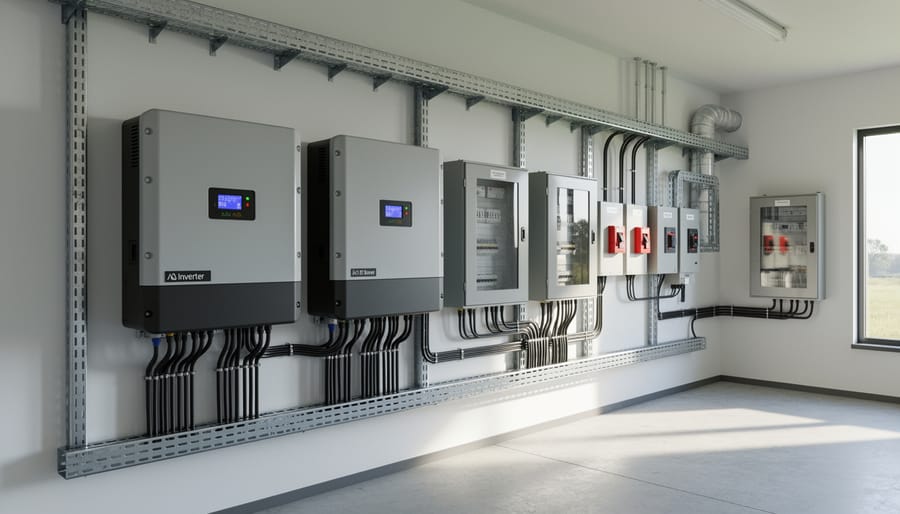
Position the inverter in a location that meets manufacturer clearance specifications, typically 12-18 inches on all sides for adequate ventilation and service access. Wall-mounted inverters should be installed at eye level (approximately 5 feet from finished floor) to facilitate monitoring and maintenance. Verify the mounting surface can support the inverter weight and that ambient temperature remains within the unit’s operating range, generally 32°F to 104°F.
Mount the DC disconnect within sight of the inverter and within reach of the solar array disconnect point. Install the AC disconnect between the inverter output and the main service panel, positioning it where utility personnel can access it without entering occupied spaces. Both disconnects must be clearly visible and rated for the system’s maximum voltage and current.
Install rapid shutdown equipment according to NEC 690.12 requirements. Module-level power electronics (MLPEs) such as optimizers or microinverters satisfy this automatically. For string inverters, mount the rapid shutdown initiator near the main service disconnect and run control wiring to array-level shutdown devices. Verify all equipment communicates properly and that shutdown occurs within one second when initiated.
For battery-integrated systems, position the energy storage unit according to manufacturer specifications regarding temperature range and ventilation. Install the battery disconnect, integrate the battery management system with the inverter, and configure charging parameters through the inverter interface. Confirm all DC connections maintain proper polarity and that the battery system communicates with monitoring platforms. Ground all metal enclosures to the system grounding electrode.
Step 5: Complete Electrical Integration and Metering
With the array wired and inverter installed, electrical integration connects the solar system to the building’s main service panel and utility infrastructure. This phase requires strict adherence to NEC Article 705 for interconnected electric power production sources.
Main Service Panel Connection
Install a dedicated breaker for the solar system in the main panel using the 120% rule (NEC 705.12(D)(2)) to determine proper breaker sizing and placement. The solar breaker must be positioned at the opposite end from the main breaker, allowing current to flow through the busbar. Label the breaker clearly as a power source. For systems exceeding available busbar capacity, use a supply-side connection ahead of the main disconnect or install a line-side tap per utility specifications.
Production Meter Installation
Mount the production meter in an accessible location following manufacturer specifications. Wire the current transformers (CTs) around the solar output conductors before the main panel connection, verifying correct polarity. Configure the meter to match system voltage and inverter output characteristics. Test communication with the monitoring platform before closing the panel.
Utility Meter Upgrades
Coordinate with the utility for any required meter replacement to enable net metering. Some utilities mandate bidirectional meters or smart meters capable of recording both consumption and export. Verify the existing meter socket accommodates the new meter configuration. Document the final meter serial number for PTO applications.
Final Grounding Verification
Confirm all grounding electrode conductor connections to the grounding electrode system, verifying torque specifications. Test bonding continuity between the solar equipment grounding system and the main service grounding system using a low-resistance ohmmeter. Document measured resistance values below 25 ohms for code compliance.
Step 6: System Labeling and Documentation
Complete and accurate system labeling is a non-negotiable National Electrical Code requirement that protects maintenance personnel, emergency responders, and future installers. Improper or missing labels are among the most common inspection failures and create serious safety hazards.
Install permanent, weather-resistant labels at every critical system component. The main service panel requires labels indicating the presence of a solar electric system and identifying the location of all disconnects. Each disconnect switch needs clear identification showing whether it controls AC or DC circuits, along with voltage and current ratings. On the inverter, affix labels showing maximum AC and DC voltage, operating current, and shutdown procedures.
NEC 690.56 mandates specific verbiage for rapid shutdown labels, typically stating “SOLAR SYSTEM EQUIPPED WITH RAPID SHUTDOWN” with the shutdown button location clearly identified. Emergency responders need immediate visibility of these labels from the street or main entrance. Place additional labels at all junction boxes, combiner boxes, and conduit entry points indicating conductor types and circuit paths.
Update the main panel circuit directory to reflect the solar backfeed breaker, noting its amperage and that it supplies power rather than consuming it. Many inspectors verify this specifically.
Prepare as-built documentation including final string layouts, actual wire gauges used, torque values applied, deviation from original plans, and installation date. Photograph each major installation phase, especially connections that will be concealed. Package this documentation with warranty information, commissioning test results, and manufacturer cut sheets for the equipment owner’s permanent records.
System Testing, Verification, and Commissioning
Before energizing any solar installation, systematic testing confirms that all components meet NEC requirements and design specifications. Start with insulation resistance testing using a megohmmeter, measure between conductors and from each conductor to ground. Acceptable readings exceed 1 megohm for residential systems and 10 megohms for commercial arrays; anything lower indicates moisture intrusion, damaged insulation, or improper terminations that must be corrected immediately.
Verify open-circuit voltage at each string before connecting to the inverter. Measure with a true-RMS multimeter at dawn or dusk to avoid arc flash hazards during high-production hours. Compare readings against calculated values from module datasheets, variance exceeding 5% signals mismatched modules, shading issues, or wiring errors. Check polarity at every connection point, then measure short-circuit current to confirm string performance matches design expectations.
Inverter commissioning follows manufacturer-specific procedures but universally requires verification of input voltage ranges, MPPT tracking functionality, and grid synchronization parameters. Configure rapid shutdown systems and confirm emergency shutdown sequences operate correctly. Initialize monitoring systems and verify data transmission, modern solar asset management platforms and barcode scanning software streamline this process for installers managing multiple sites.
Conduct performance validation under actual load conditions. Record AC output voltage, current, and power factor at the point of interconnection. Compare production data against PVWatts or similar modeling software predictions, accounting for weather conditions during testing. Document all measurements, test equipment calibration dates, and any deviations from design specifications in your commissioning report. Many contractors integrate these records into fixed asset programs for long-term system tracking and warranty management.
Final Inspection and Permission to Operate
The final inspection marks the transition from construction to operation and requires coordination with both the authority having jurisdiction (AHJ) and the utility company. Schedule the AHJ inspection only after completing all installation work, system testing, and proper labeling. Most jurisdictions require 24-48 hours advance notice, though scheduling timelines vary significantly by location.
Before the inspector arrives, verify that all NEC-compliant labels are in place, including AC and DC disconnect labels, rapid shutdown placards, and inverter warning signs. Ensure the installation matches the approved permit plans exactly. Common inspection failures include missing labels, improper grounding connections, inadequate working clearances around electrical equipment, and conduit fill violations. Have your permit documents, approved plans, and equipment spec sheets readily available.
During the inspection, the AHJ inspector will verify structural attachments, electrical connections, proper equipment ratings, and code compliance. They typically check torque on critical connections, ground continuity, and proper conductor sizing. Address any identified deficiencies immediately and schedule a re-inspection if necessary.
Once the AHJ signs off, submit the final inspection documentation to the utility along with their interconnection application. The utility conducts its own inspection, focusing on metering equipment, disconnect accessibility, and anti-islanding protection. After utility approval, they issue Permission to Operate (PTO) documentation. Only after receiving written PTO can you energize the system and begin feeding power to the grid. PTO processing times range from days to several weeks depending on utility procedures.
Successful solar installation demands adherence to a precise sequence of tasks, where skipping steps or reversing order creates cascading problems that compromise system performance and safety. From initial site assessment through final PTO approval, each phase builds upon the previous work, mounting integrity determines panel security, proper wiring ensures electrical safety, and thorough testing validates system readiness. Professional installers who follow established protocols consistently deliver systems that perform to specification, pass inspection on the first attempt, and require minimal corrective maintenance.
How long does a typical residential solar installation take?
Most residential installations require one to three days of on-site work for a standard crew, though permitting and inspection processes extend the total timeline to 4-8 weeks from contract signing to PTO.
What crew size is required for solar installations?
A two to four person crew handles most residential projects efficiently, while commercial installations typically need four to eight installers depending on system size and complexity.
How do weather conditions affect installation schedules?
Rain, high winds above 25 mph, and icy conditions require work stoppage for safety reasons, and installers typically add 20-30% schedule buffer for weather delays in planning.
The distinction between adequate and exceptional solar installation lies in attention to detail during every phase. Proper torque on electrical connections prevents hotspots, correct flashing installation eliminates roof leaks, and accurate documentation streamlines future service calls. When installers treat each step as critical rather than routine, they establish a foundation for 25-plus years of reliable energy production with minimal intervention beyond standard cleaning and monitoring.